Connections
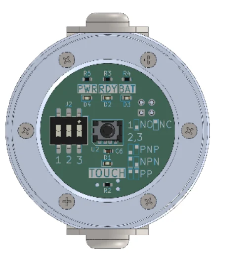
The selection of the state and type of output signals is done using a switch on the printed circuit board as shown in the following figure. The meaning of the switches and their settings is shown directly on the printed circuit board.
| Setting | Options | Factory setting |
|---|---|---|
| Output signal status – switch 1 | NO, NC | NO |
| Output signal type – switch 2,3 | PNP, NPN, Push-Pull | PNP |
The factory setting of the output signals is PNP / NO.
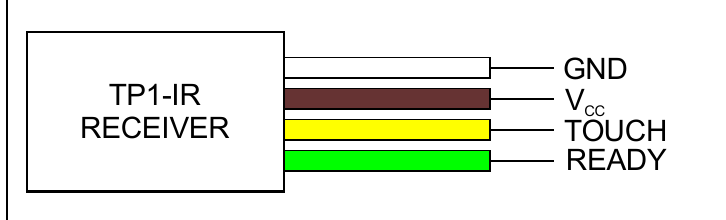
Wire marking
| Colour | Wire |
|---|---|
| GND – white | |
| VCC – brown | |
| TOUCH – yellow | |
| READY – green |
Note
The output stages behind these settings are shown under Wiring Diagrams.